|
|
Post by woodyz on Jan 18, 2014 21:19:24 GMT -7
have been looking at water wheels. Both as a power source and for grinding. Most designs appear to be Vertical, where the water runs down and over the wheel. But that takes quite a bit of elevation drop to get water at any speed to flow down and over. Then there are horizontal models where the water wheel can be submerged under the mill/power station. Except for removing the water for a period of time so the wheel can be constructed they seem to me to be an easier option for a small group of people to construct and operate. May be taking advantage of the seasons when the water is lower and higher to do the battery charging or grinding.   |
|
|
|
Post by Cwi555 on Jan 19, 2014 12:05:48 GMT -7
have been looking at water wheels. Both as a power source and for grinding. Most designs appear to be Vertical, where the water runs down and over the wheel. But that takes quite a bit of elevation drop to get water at any speed to flow down and over. Then there are horizontal models where the water wheel can be submerged under the mill/power station. Except for removing the water for a period of time so the wheel can be constructed they seem to me to be an easier option for a small group of people to construct and operate. May be taking advantage of the seasons when the water is lower and higher to do the battery charging or grinding.   When the wheel is made of wood, you want it exposed and vertical every time. Maintenance plays a large roll in this as well. Then we get to head pressure. For a lower head pressure, the impeller/underground version is better. |
|
|
|
Post by woodyz on Jan 19, 2014 19:00:18 GMT -7
I didn't intend on using wood, I am thinking more along the lines of 30 gallon plastic buckets cut in half or thick wall 6" PVC pipe cut in half. I am looking a several DIY articles that I will post back on as I explore the different options. Remember I am looking at a DIY small operation that can be done in a slow moving river current or in a stream or creek. Even a large lake behind a dam produces some current. www.micro-hydro-power.com/how-to-measure-water-head.htmwww.micro-hydro-power.com/how-to-measure-water-flow.htmIf I ran a pipe under water and then reduced the pipe size to increase the flow and directed the increased flow on to my blades I could turn a wheel of some size. Here is an article using a five gallon bucket to produce enough electricity to charge small appliances like a cell phone. www.pocketburgers.com/2008/07/in-depth-look-at-diy-bucket.htmlIts all a matter of scale, some knowledge and adapting materials from what you have. |
|
|
|
Post by Cwi555 on Jan 20, 2014 11:41:27 GMT -7
Bernoulli's principle applies. Remember the difference between dynamic pressure/kinetic energy and static pressure/potential energy. Decreasing the pipe size will increase the velocity of the water but decrease it's pressure.
|
|
|
|
Post by thywar on Jan 20, 2014 14:48:09 GMT -7
Ok.. I'm like really jumping off a tall cliff here by even trying to ask questions/partake in this discussion.. but isn't the velocity what he would be looking for if he was just trying to turn the wheel?
|
|
|
|
Post by Cwi555 on Jan 20, 2014 16:58:46 GMT -7
Ok.. I'm like really jumping off a tall cliff here by even trying to ask questions/partake in this discussion.. but isn't the velocity what he would be looking for if he was just trying to turn the wheel? For a given volume of water, there is a finite amount of potential energy. Increasing the velocity of the water flow via Bernoulli's principle, reduces the pressure. Picture a garden hose nozzle.  If you have 45 PSI in your home water system, that is all you have and cannot create more (volume/head) by any means other than higher head pressure, pumps etc which would change the effective volume. Water is not considered to be compressible for all practical purposes, therefore you cannot store any more energy for a given volume. A + change in the volume would increase the potential energy. With a static volume, you get what you get. The term flow implies an increased volume pushed through a given system. That carries us back to static volume with no other qualifiers. For a given head pressure, a smaller nozzle orifice will have a greater speed and lower output (flow), while a larger nozzle orifice will have a lower speed and higher output. That is why I commented. Reducing the orifice size does not increase flow, in fact it does the opposite. What it does do is change the velocity and efficiency of work for the energy/water that does get through. With that in mind, a smaller area on the turbine blades, and a lighter weight turbine is required to convert that energy as efficiently as possible to take advantage of that velocity. |
|
|
|
Post by woodyz on Jan 20, 2014 19:19:25 GMT -7
Yes I understand. I think I have a wording problem rather than a physics problem. I am not as good with words as CWI. I can think out a lot of things I can't verbalize. Drives my son nuts because I have to show him rather than tell him.
With the reduction I would be focusing the energy/pressure that is there to where I need it to be concentrated. I increase the water pressure in my shower heads by reducing the feed pipe to them. I don't get as much water in GPM but I get a better shower.
I am setting up a model using cut water bottles so I can measure my differences in revolutions per minute based on how the bottles are cut and how they are arranged.
|
|
|
|
Post by woodyz on Jan 21, 2014 5:11:45 GMT -7
I've decided to use a 16" bicycle wheel as my test water wheel. It's easy to balance and I would have plenty of bearings and can mount it on a spinle. I am cutting the bottles so that I can attach them to the spokes I would not be able to use this underwater due to the bearings being exposed. But I can use it to test different pressures and different configurations for the cutting of the bottles.
Then I think I will use the wheel and attach cut pieces of PVC, again to count revolution and to test configurations of the cut and angle of the PVC.
Unlike the shower where reducing the size of the pipe increases the pressure behind the water stream, using that method pressure is not going to increase because the flow has no build up behind it.
So the method to increase the revolutions with a stream or river flow will be starting with a larger wheel and stepping what is driven by it down until I get the revolutions I need. Kind of like the gears in a clock, the smaller the faster.
Again I will go to bicycle parts, a 10 speed has several size gears that I can use to step down my test wheel so I can see if I can increase the revolutions to something useful.
Maybe going to a 20" wheel and stepping it down to 16", 14", etc. They would be available in a SHTF situation I just have to figure out the one under water bearing assembly. Maybe a boat motor propeller shaft, but with a larger wheel attached.
Well that's my project for this week, making it work using a hose and see how much I can increase the revolutions by stepping the wheels down in size. By using bicycle gears I can also use bicycle chains, but again not under water.
Well one thing at a time.
|
|
|
|
Post by tjwilhelm on Jan 21, 2014 10:05:45 GMT -7
Because you used the phrase "micro-hydro," I assume you are looking to build a small hydro-powered electric power plant...true?
If so, you will most likely be using a vertical-shaft (horizontal plane of rotation) machine. Most of the micro-hydro plants are "head" driven machines, vs. a so-called "kinetic" wheel. Kinetic wheels are typically horizontal-axis (vertical plane of rotation) machines; and, they are not as efficient as head-driven machines. Kinetic wheels are your old-fashion water wheels with the bottom half of the wheel dipped down into a flowing stream of water with very little head pressure. They just extract energy from the kinetic flow of the stream or river.
For a good micro-hydro installation, you need to have sufficient head pressure, typically measured in "feet of head." This is the number of feet from the high point of the water supply to the discharge point of the turbine. If you're looking at a manufactured turbine (Lil Otto; Stream Engine; Harris; etc.) they should provide all the site assessment and installation info you need.
|
|
|
|
Post by woodyz on Jan 22, 2014 19:43:49 GMT -7
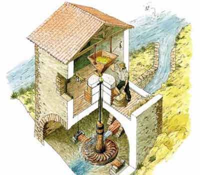
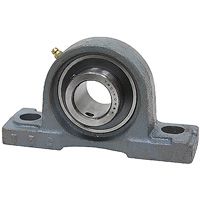
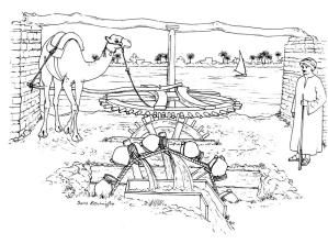
From everything I am reading I am becoming convinced I won't be using the stream flow and will need some head pressure. The problem I had with that in my mind was that I would have to be down hill or behind a dam or pump water. Then I saw this underflow type wheel. Don't know why I just always picture the flow had to be from the top.  So with this type of model I could make due with only a few feet of head space. I understand the amount of head space will determine rotation speed and thereby out put. I have a conversion chart for that. Now I need to work on the design. As bad as I don't want to I am thinking I should buy and store some bearings to have on hand. Such as these, less than $10, but the point I am still aiming for is to accomplish a DIY model that will allow what one has on hand in their junk pile and make something that works.   We used to use old line cable spools for a table, I would think they would be a good place to start to construct a water wheel. Ofcourse I shouldn't forget the option to use animal power to replace head space and a pump. I just have to convince my wife to walk in a circle for 4 hours a day. Eureka I have it. All I need to is tie her up short to the wheel and tack a credit card in front of her just out of reach.  |
|